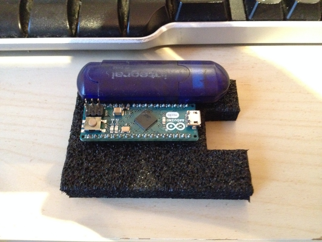
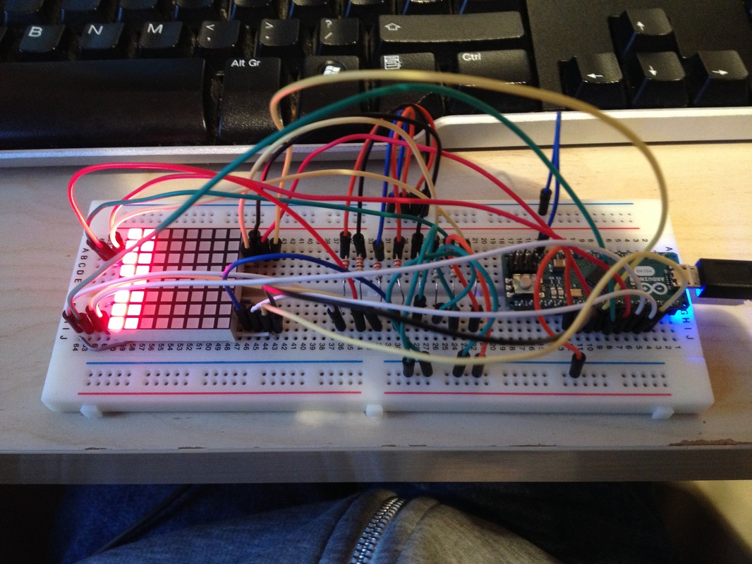
So in the last blog post I put a teaser picture at the bottom which showed a grid of lights hooked up the an Arduino Micro Microcontroller. As usual I am not good at holding suspense, I was too eager to get this blog post out, so you didn't have to wait very long to find out what's going on in that picture! Introducing, on it's debut performance here on Tales of a Rookie.... The Dot Matrix Display. This is the point where you realize how bad of a pun the title is...
So what is a Dot Matrix Display and what is it used for? I decided that for the basics I would once again do a video, as especially this time the visual aspect of a video makes this a lot easier to understand and a lot cooler! So without further ado here is me from the past telling you how this thing works on a basic level!
So what is a Dot Matrix Display and what is it used for? I decided that for the basics I would once again do a video, as especially this time the visual aspect of a video makes this a lot easier to understand and a lot cooler! So without further ado here is me from the past telling you how this thing works on a basic level!
So hopefully now you understand what a Dot Matrix Display is, how it works and what it is used for! So for those of you who want to know a little bit more detail about how this works, how the chips work and how the code works! Here we go!
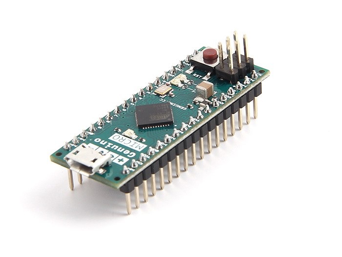
I thought it would be best to start with an explanation of what each of the Integrated Circuits do, as then we can better understand how all of these different packages are tied together to create the setup you have seen in the video. As stated in the video there are two 74HC595 Shift Registers and a single ULN2003A Transistor Array (as well as a BC639 Transistor to increase the transistor count to 8), as well as the Arduino Micro Microcontroller and the Dot Matrix Display. All of these chips tie together to make two main sections in the system, the column driver and the row driver sections. Both of these sections rely on a 74HC595 Shift Register so lets start with that!
I thought it would be best to start with an explanation of what each of the Integrated Circuits do, as then we can better understand how all of these different packages are tied together to create the setup you have seen in the video. As stated in the video there are two 74HC595 Shift Registers and a single ULN2003A Transistor Array (as well as a BC639 Transistor to increase the transistor count to 8), as well as the Arduino Micro Microcontroller and the Dot Matrix Display. All of these chips tie together to make two main sections in the system, the column driver and the row driver sections. Both of these sections rely on a 74HC595 Shift Register so lets start with that!
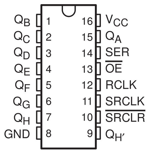
The 74HC595 is a 7400 Series Serial Input Parallel Output (SIPO) Shift Register, this means it takes Serial Input in from the main controller of the system (in this case the Arduino) and converts it to a parallel signal. As a quick explanation, Parallel is when you use one track on your board for one bit and Serial is where you are sending all of the bits down a single track sequentially (one at a time). This particular shift register has two sets of storage registers (think of them as little boxes that store one bit of information), the data is shifted into the initial storage register set using the SER and SRCLK pins. When the data is completely loaded the RCLK pin is pulsed which loads the data into the second set of storage registers. The output pins reflect the states of the second set of storage registers. This technique removes the flicker on the output pins that occurs on shift registers that only have one storage register set. The ultimate purpose of this chip in this setup is to reduce the amount of IO required on the Microcontroller to drive the 8 by 8 display. Without this setup we would need three quarters of the available IO the Arduino Micro has to drive the display. Not to mention the code required to run the display would take much longer to right, as you would have to set each pin individually.
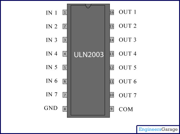
The ULN2003A Transistor Array is a essentially a set of transistors in a single package. The inputs of the chip are the bases of the Transistor and the Outputs are the Collectors. When an input is sent high the corresponding output is directly connected to ground; for example if I send a high signal to input five then output five will be pulled low. In this application the chip is being used as a current sink device. I have used this chip to pull the rows of the display low so that there is a potential difference of 2V across the LED's of the display. The current is essentially "sunk" through this chip to ground. The use of this chip is more of a convenience than anything else and a set of eight individual transistors would work just as well.
It is important to note that this chip was put in series with 220 Ohm Resistors on each of the rows to limit the amount of current being drawn by the display; so that nothing in the circuit blows due to over current.
Finally the Dot Matrix Display is essentially another part that makes life easier for us. It wires up the LED's inside in such a way that only 16 pins are required to interface every LED on the whole display. Once again without this pin saving mechanism we would need a Microcontroller with a much higher IO count to drive the display even with the Shift Registers we have already implemented.
If you want more information on any of these chips then there are already great tutorials online on the Arduino Site and Forums detailing exactly how to use these chips with your Microcontroller!
So, how is this all tied together to make a fully functioning system?
Well as explained in the video, essentially there is a column driver section and a row driver section. The row driver section is made up of the 74HC595 Shift Register and the ULN2003A transistor array (as well as an extra transistor to bump up the amount of transistors to eight. This section is acting as a current sink as well as an inverter for the signals coming from the 74HC595. This is so we can actually create a 2V potential difference across the LED's in the matrix. The column section is literally a 74HC595 driving the columns high, again so that the correct potential difference can be created across the LED's in the display.
In terms of current this is fine as we are not drawing enough current through each of the chips for it to affect them. If you wanted something brighter and consequently higher power, you would possibly have to use a transistor array for the column driver as well. Except this one would direct correctly to Vcc rather than ground.
Finally we are using the Arduino to provide all of the signals that will actually drive the display and create our images! The code that is running on Arduino can be found in the downloads section of this website, so be sure to look there if you want to use the code I wrote in your own project. Bare in mind that you will have to use pretty much the same setup as me if you want to use my code without adapting it to your specific needs. The important part of the code that needs to be addressed here is the shiftOut() command that is regularly seen throughout the code. This is a function available in the Arduino libraries that makes it extremely easy to shift serial data out to the shift registers in the system. All you need to provide is the data pin, clock pin, the order in which you want to shift out the bits (i.e Least Significant Bit First or Most Significant Bit First) and the data you actually want to shift out! For more information please see this link:
That's pretty much it for this project! You will be seeing more of this Dot Matrix Display in the future as I plan to write some code for scrolling text and displaying images!
Thanks for reading!
Sam
Thanks for reading!
Sam